


HDLBits问题ece241_2014_q7a。我的解法的仿真结果与参考不一致
以下是原始题目:
设计一个1-12的计数器,具有以下输入和输出:
重置(Reset):同步、有效位为高的复位,使计数器强制为1
使能(Enable):计数器运行时将该信号置高
时钟(Clk):上升沿触发的时钟输入
Q[3:0]:计数器的输出
c_enable、c_load、c_d[3:0]:送往所提供的4 位计数器的控制信号,便于验证正确的操作。
你有以下可用的组件: 下方的4 位二进制计数器(count4),它具有使能和同步并行加载输入(load的优先级高于使能)。count4模块已提供给你。请在你的电路中实例化它。
逻辑门
module count4(
input clk,
input enable,
input load,
input [3:0] d,
output reg [3:0] Q
);
c_enable、c_load和 c_d的输出信号分别是内部计数器的enable、load和 d输入。它们的目的是为了让这些信号可以被检查是否正确。
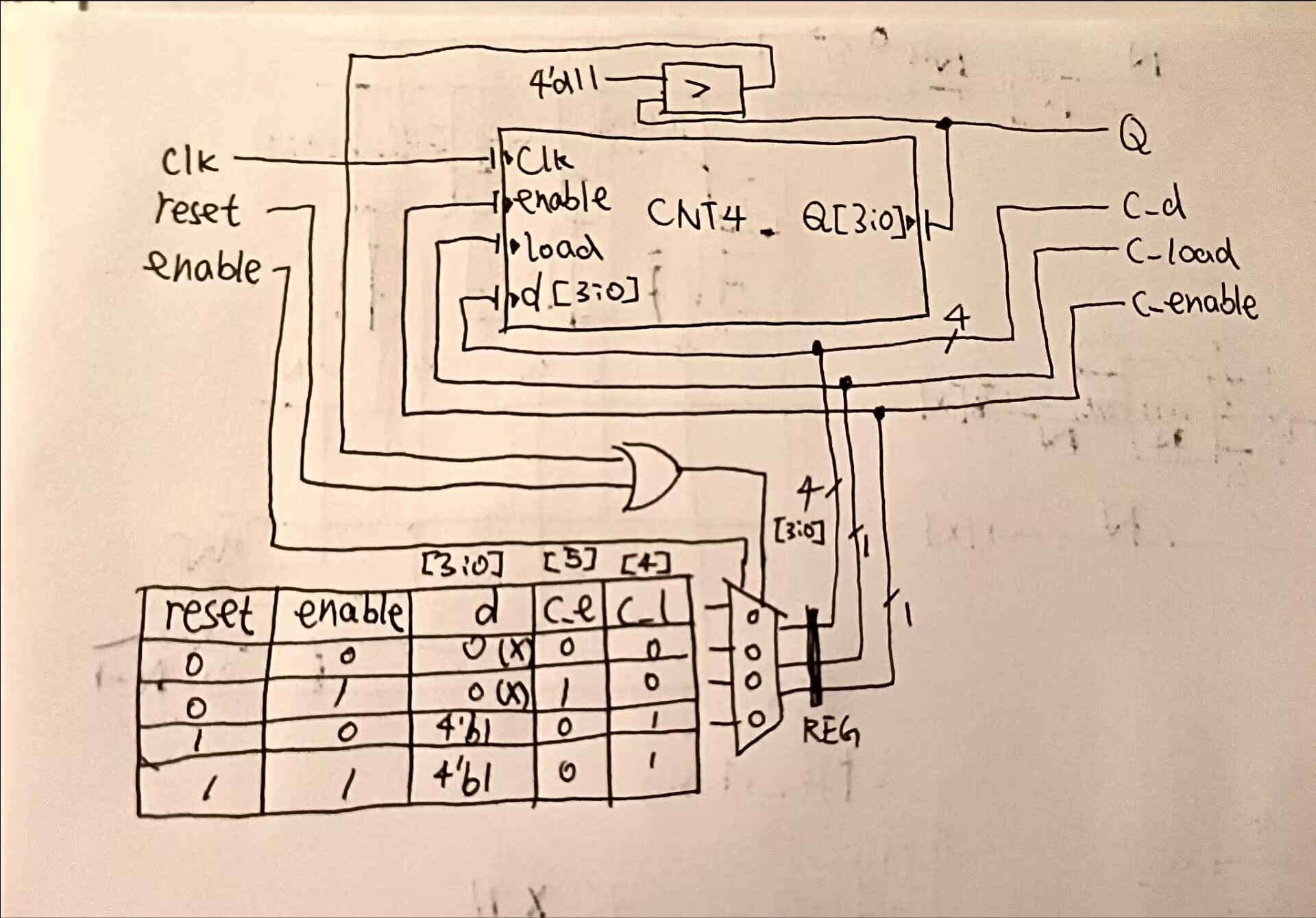
我注意到这个问题可以用真值表和组合逻辑来解决。
这是我试图实现的电路:
这是我的失败解:
module top_module (
    input clk,
    input reset,
    input enable,
    output [3:0] Q,
    output c_enable,
    output c_load,
    output [3:0] c_d
); //

    count4 the_counter (clk, c_enable, c_load, c_d ,Q );

    reg [5:0] v_ctrl;
    wire reset_judge;

    wire c_enbuf;

    assign c_enbuf = v_ctrl[5];
    assign c_load = v_ctrl[4];
    assign c_d = v_ctrl[3:0];

    assign c_enable = c_load?0:c_enbuf;

    always @(*) begin
        case({{reset|(Q>11)},enable})VerilogVerilog
            2'b00:v_ctrl = {1'b0,1'b0,4'b0};
            2'b01:v_ctrl = {1'b1,1'b0,4'b0};
            2'b10:v_ctrl = {1'b0,1'b1,4'b1};
            2'b11:v_ctrl = {1'b0,1'b1,4'b1};
        endcase
    end
endmodule
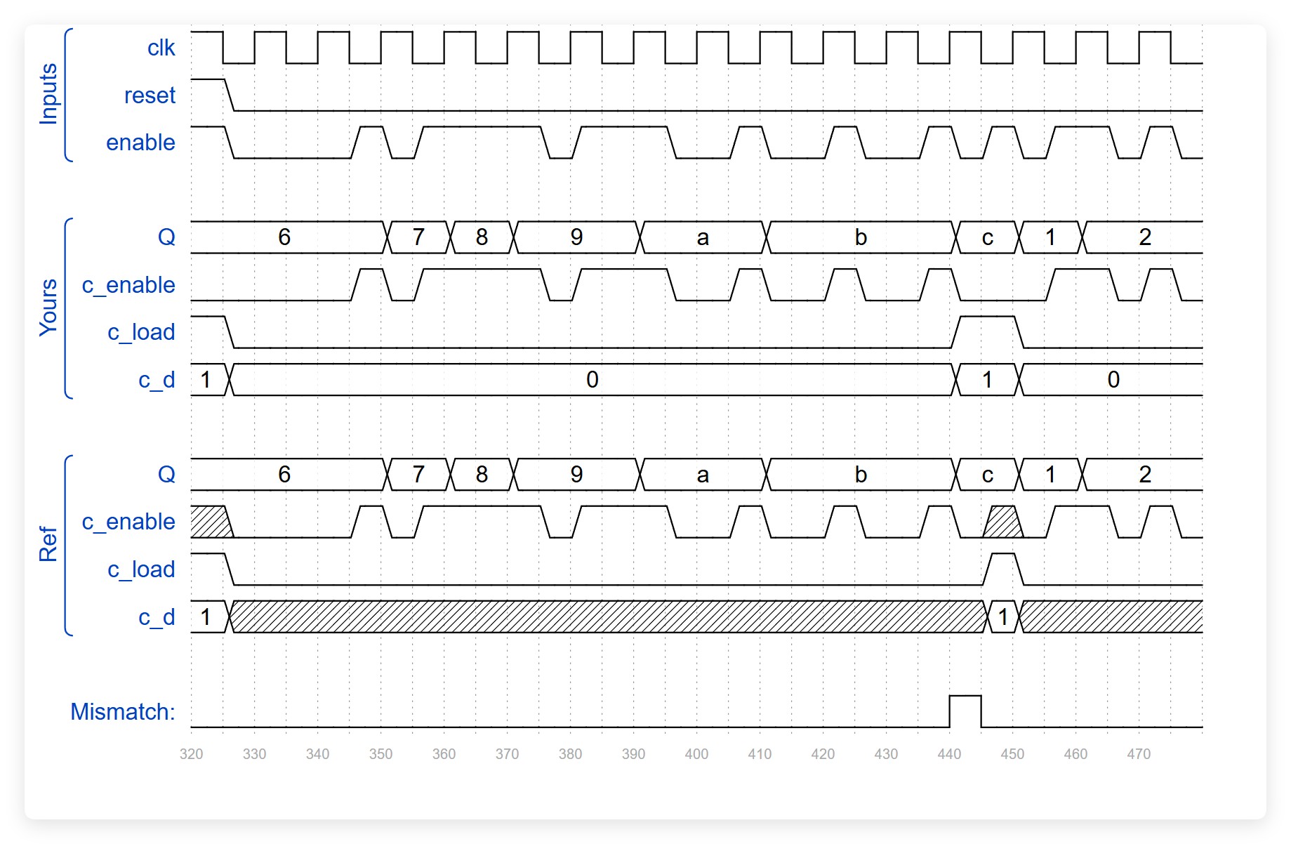
结果是,在440处出现不匹配:
一个 通过 的解:
module top_module (
    input clk,
    input reset,
    input enable,
    output [3:0] Q,
    output c_enable,
    output c_load,
    output [3:0] c_d
);

    wire wrap;
    assign wrap = (Q == 4'd12);

    assign c_d = 4'd1;

    assign c_load   = reset | (enable & wrap);
    assign c_enable = enable & ~c_load;

    count4 the_counter (
        .clk(clk),
        .enable(c_enable),
        .load(c_load),
        .d(c_d),
        .Q(Q)
    );

endmodule
我的问题:
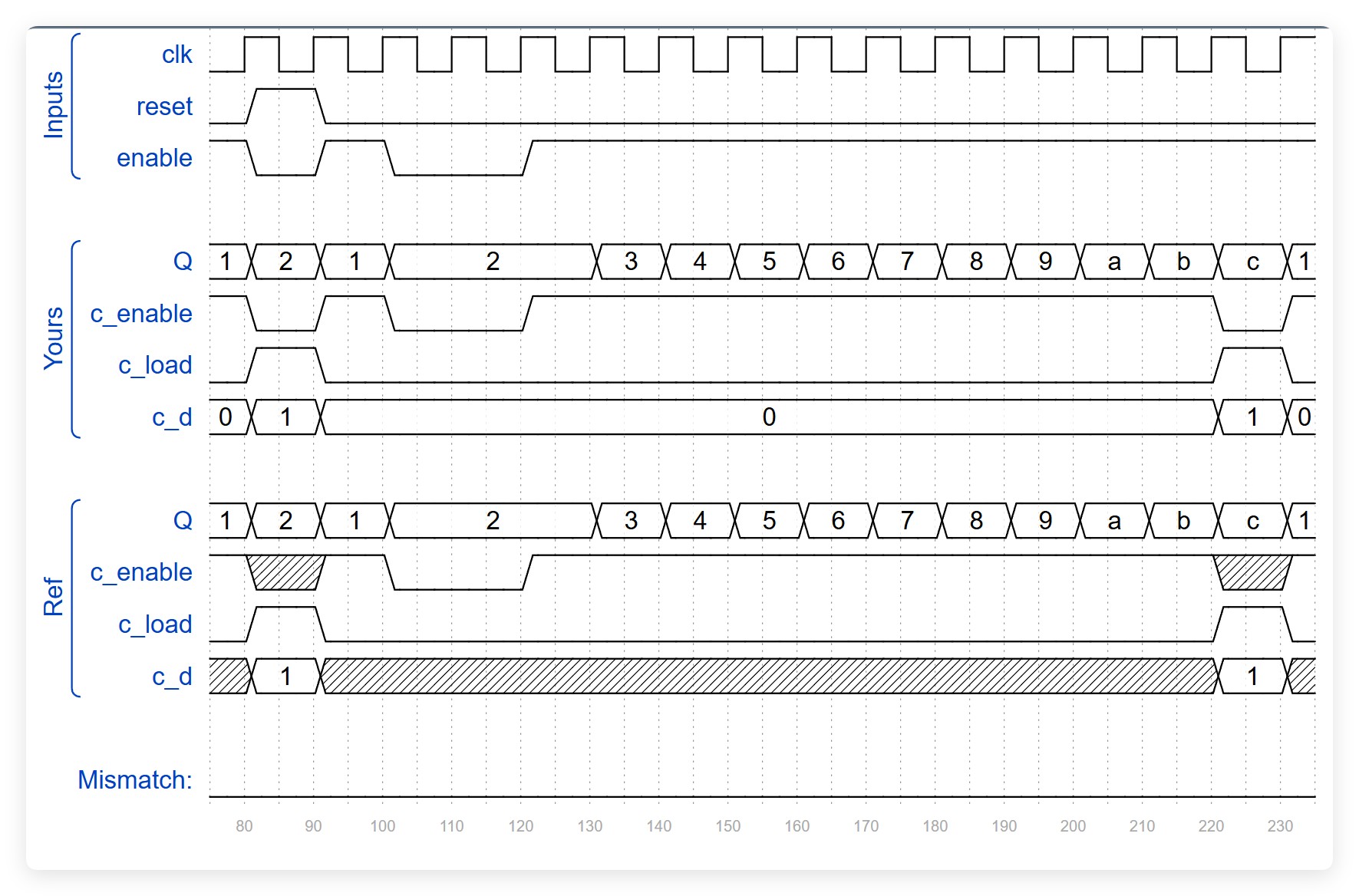
如波形所示,"reset" 和 "enable" 都处于0(低电平)状态,但 "c_load" 的行为并没有跟随我的真值表。这是Verilog语言的特性、合成器的问题、还是仿真器的问题,还是我错误使用语言导致的bug?我想知道为什么会这样。
这个失败的解是凭借我独立思考最接近成功的版本。
这篇帖子也没有帮助解答我的问题:
questions/55430880/a-problem-on-hdlbits-design-a-1-12-counter-with-the-following-inputs-and-output
给定的模块:
module count4(
    input clk,
    input enable,
    input load,
    input [3:0] d,
    output reg [3:0] Q
);
顶层模块:
module top_module (
    input clk,
    input reset,
    input enable,
    output [3:0] Q,
    output c_enable,
    output c_load,
    output [3:0] c_d
);
解决方案
HDLBits网站只适用于最基本的逻辑设计,但在本示例这类设计时,它并不实用。以下是与该示例相关的一些具体问题:
- 我们看不到
count4设计的Verilog代码。 - 我们看不到站点使用的测试基准的Verilog代码。
- 我们看不到内部信号的波形来调试失败的仿真。
- 设计的描述存在歧义。尚不清楚
enable输入是否与时钟同步。底部的波形似乎表明它是异步 的。如果是这样,则会出现仿真竞争条件,导致结果不可预测。
我建议放弃这种方法。你应该自行编写 count4 设计的Verilog代码,以及你自己的 测试基准Verilog代码 来验证其功能。请在HDLBits站点之外使用另一台仿真器运行仿真,并导出所有内部信号的波形。
之后你就可以开始创建计数到12的设计并进行仿真。
此外,这一行存在非法语法:
case({{reset|(Q>11)},enable})VerilogVerilog
VerilogVerilog 不应该出现在那里。
相关文章